
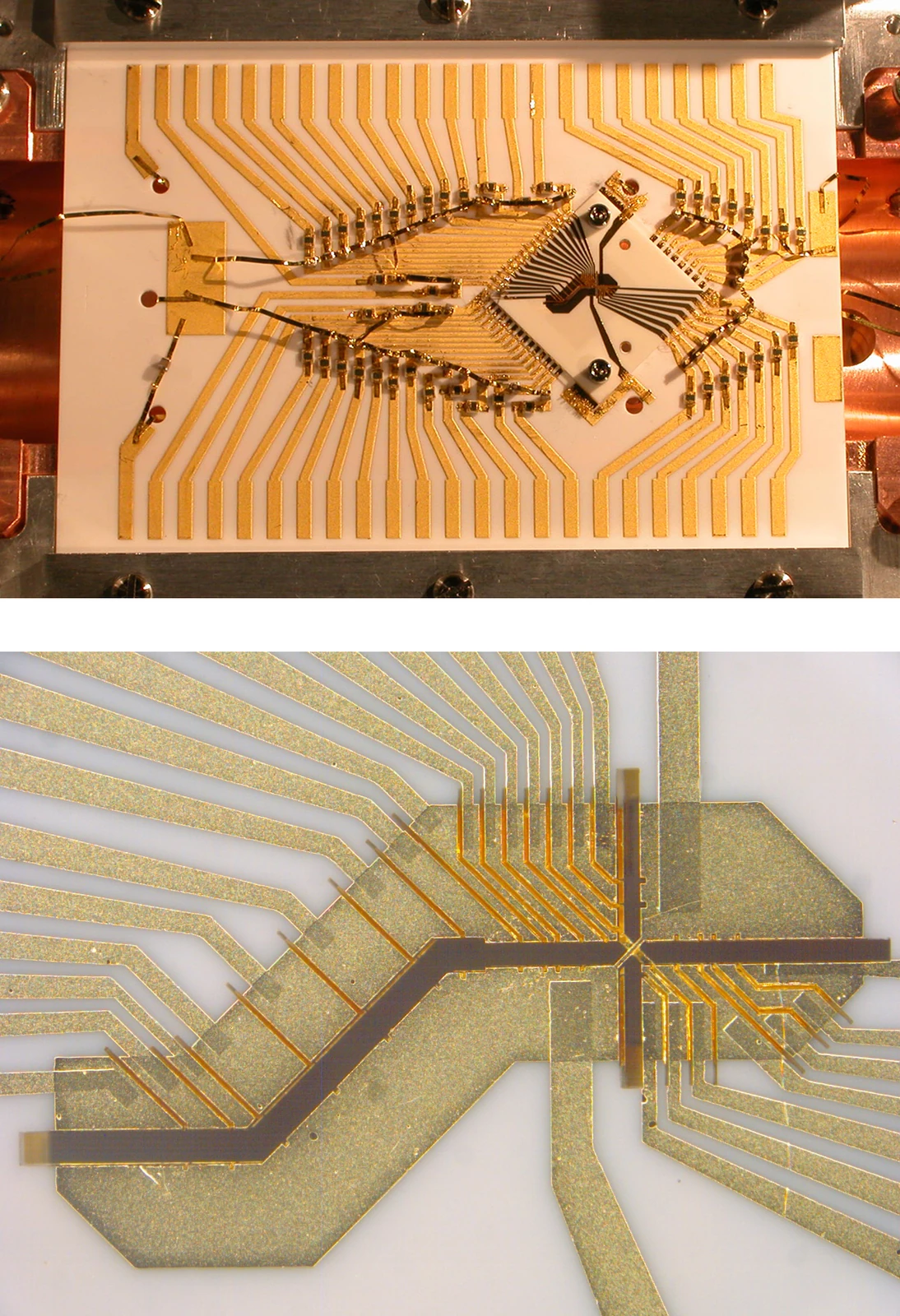
Two scales of an X-junction ion trap
The two views answer different questions. The wider frame shows the assembled component and its connections; the close-up reveals the crossing channels in the trap. NIST’s description links these channels to the movement of ions through a junction. Present the panels together so readers can connect device geometry with the packaged object. If a publication uses only one panel, identify the crop and retain the original source link. Do not imply that the photograph directly records ions moving or establishes the error of a transport operation. It documents the apparatus on which those measurements would be made.
- Organization
- NIST
- Image type
- Photograph
- Capture date
- 2011-07-15
- Photographer / creator
- R. B. Blakestad / NIST
- Reuse terms
- Public domain
R. B. Blakestad / NIST — Ion trap (5941060224).jpg — Public domain — https://commons.wikimedia.org/wiki/File:Ion_trap_(5941060224).jpg — https://commons.wikimedia.org/wiki/File:Ion_trap_(5941060224).jpg#Licensing.
Full original frame retained; EXIF orientation normalized where present, resized without enlargement and converted to WebP. No crop or content alteration.
Read the image
Two photographic scales connect a junction to its assembly
The source image contains two stacked photographic panels. The upper panel shows a wired assembly; the lower panel moves closer to intersecting patterned channels. NIST identifies the subject as an X-junction ion-trap arrangement. The composite is already part of the original asset, not a newly created QubitWire collage.
The two scales answer different questions. The assembly view places the device among supports and connections. The close view reveals the junction geometry that gives the trap its name. Together they help explain why a fabricated junction needs a larger structure to become an experimental system.
Transport through a junction is an operational question. The visible crossing shows intended geometry, but successful movement, motional excitation and subsequent operation must be measured. Preserve both panels so readers can connect the structural idea with its physical integration, then follow a linked technical source for demonstrated behavior.
Why keep both panels together?
Their relationship is the point of the source composition. Separating them can remove the connection between microscopic geometry and assembly context.
Does the crossing prove ions were successfully routed?
No. It shows the structure. A transport experiment and its measurements are needed to establish how routing performs.
What should a new annotation respect?
Keep existing scientific context and avoid covering important geometry. Record the date and nature of any change to the NIST image.
An independent QubitWire lesson based on this image and the cited source reading. The image does not establish a performance result.
Keep exploring
More from the same organization or hardware architecture.
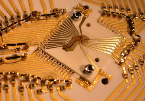 Gold electrodes for trapped ionsBlakestad/NIST · NQI gallery reuse permission
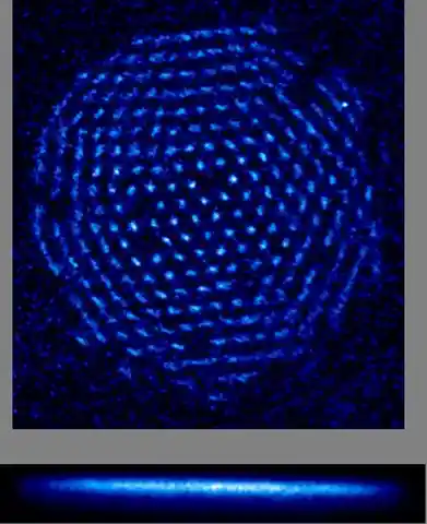 A crystal of trapped ionsNational Institute of Standards and Technology · Public domain (U.S. Government)
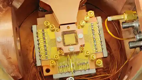 NIST’s beryllium-ion apparatusY. Colombe / NIST · Public domain (U.S. Government)
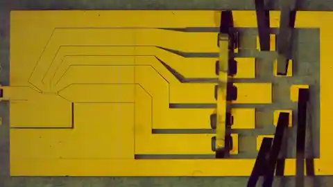 Gold electrodes for trapping ionsSigne Seidelin and John Chiaverini / NIST · Public domain (U.S. Government)
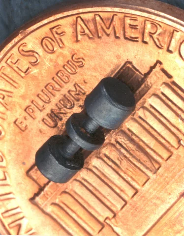 An ion trap resting on a pennyJ. Bergquist and D. Wineland / NIST · Public domain
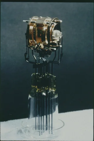 An early laser-cooling ion trapNIST · Public domain
Back to all images · Explore the interactive Model · Image rights and corrections