
Quantum in pictures
The little trap and the optical clock
A trap resting on a coin and two views of optical-clock laboratories show how a very small reference can require a substantial experimental system.
Research context: October 19, 2026 · Source review: October 20, 2026
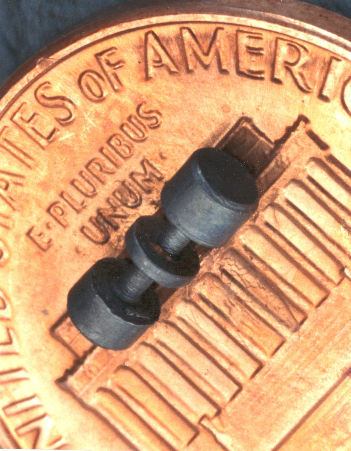
The coin is a scale reference for the trap, not a picture of the ion. That distinction makes this an unusually effective beginner image. The NIST description identifies a device used to hold a single mercury ion in an optical clock. An explanation can then separate the trapped quantum object from the electrodes and the wider equipment used to prepare and observe it. Avoid describing the entire clock as penny-sized: the photograph shows one component. The comparison is memorable precisely because the image permits a careful statement about physical scale without claiming that the surrounding laboratory has disappeared.
J. Bergquist and D. Wineland / NIST — Ion Trap (5881388433).jpg — Public domain — https://commons.wikimedia.org/wiki/File:Ion_Trap_(5881388433).jpg — https://commons.wikimedia.org/wiki/File:Ion_Trap_(5881388433).jpg#Licensing.Full original frame retained; EXIF orientation normalized where present, resized without enlargement and converted to WebP. No crop or content alteration.
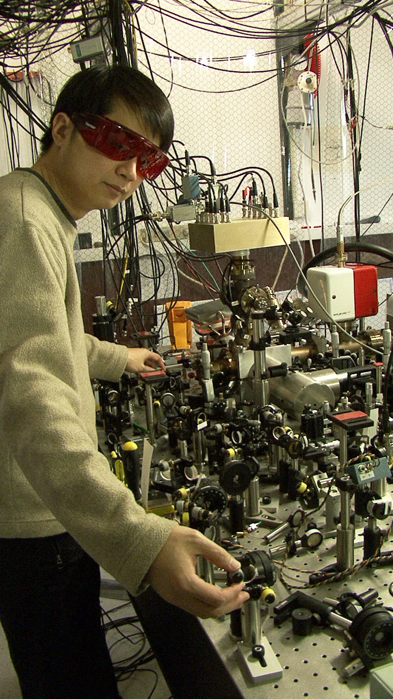
A single-ion experiment can occupy far more space than the trapped object suggests. This photograph supplies that missing scale by showing a researcher alongside the optical equipment of a quantum-logic clock. The original NIST caption used a superlative appropriate to its publication period; do not carry that old ranking into a current headline. Instead, explain the relationship between a microscopic reference and the macroscopic apparatus needed to control and compare it. The scene is a good companion to the penny-sized trap photograph, provided the article clearly states that the two images show different clock-related apparatus rather than one complete matching installation.
J. Burrus / NIST — NISTs Second Quantum Logic Clock Based on Aluminum Ion is Now Worlds Most Precise Clock (5941058358).jpg — Public domain — https://commons.wikimedia.org/wiki/File:NISTs_Second_Quantum_Logic_Clock_Based_on_Aluminum_Ion_is_Now_Worlds_Most_Precise_Clock_(5941058358).jpg — https://commons.wikimedia.org/wiki/File:NISTs_Second_Quantum_Logic_Clock_Based_on_Aluminum_Ion_is_Now_Worlds_Most_Precise_Clock_(5941058358).jpg#Licensing.Full original frame retained; EXIF orientation normalized where present, resized without enlargement and converted to WebP. No crop or content alteration.
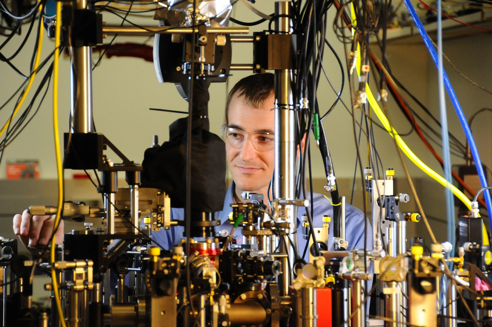
The crowded foreground makes control equipment the main visual subject. NIST identifies David Leibrandt and a quantum-logic clock, giving the picture a specific research context. Readers can use it to ask why observing one carefully chosen quantum transition involves so many macroscopic parts. Keep the explanation focused on functions such as delivering light, collecting a signal and stabilizing conditions; do not assign an exact role to each visible component without a layout reference. As an archival photograph, it can illuminate how a measurement is organized while remaining separate from present-day claims about clock precision or records.
Burrus / NIST — David Leibrand and Quantum Logic Clock (13586705734).jpg — Public domain — https://commons.wikimedia.org/wiki/File:David_Leibrand_and_Quantum_Logic_Clock_(13586705734).jpg — https://commons.wikimedia.org/wiki/File:David_Leibrand_and_Quantum_Logic_Clock_(13586705734).jpg#Licensing.Full original frame retained; EXIF orientation normalized where present, resized without enlargement and converted to WebP. No crop or content alteration.
The trap fits on a penny. In NIST’s close-up photograph, a small metallic device sits on the coin, making its size understandable without a technical drawing. The source identifies it as an ion trap associated with a mercury-ion optical clock. The coin is a scale reference; the trapped ion and the complete timekeeping instrument are not visible as separate objects in this frame.[1]
Now widen the view. A 2010 photograph shows James Chin-wen Chou beside equipment for NIST’s aluminum-ion quantum-logic clock. Another archival view places David Leibrandt behind an optical table. The work surfaces are crowded with the components needed to prepare, illuminate, control and measure an atomic system. The sequence moves from a small piece of the apparatus to the larger setting in which a clock can be operated.[2][3]
The mercury trap and the aluminum-clock laboratories represent different devices. They belong together here because they illustrate a shared engineering problem: a useful atomic reference must be accessed without losing the conditions that make it useful. Holding an ion in place is one task. Providing the right optical signals and interpreting its response are others. The size of the atom does not determine the size of that supporting system.
NIST’s 2010 description explains why its aluminum clock used a partner ion. Aluminum supplied the clock transition, while a magnesium ion assisted with cooling and readout. Quantum-logic methods made information about the aluminum ion accessible through a more convenient partner. The phrase “quantum logic” therefore describes a method used within the measurement. It does not turn the clock into a general-purpose computer running a collection of unrelated algorithms.[4]
An intuitive way to follow the idea is to assign two roles in an original diagram. One ion is the reference being interrogated; the other helps reveal the result. Their controlled shared motion provides a way to connect those roles.
A final arrow leads to a measured outcome and a feedback loop that adjusts the probing laser. The diagram should identify this as an explanation of the aluminum-clock method, separate from the photographed mercury trap.
The laboratory views also help explain why clock performance is assessed through measurement and comparison. An attractive small trap does not reveal a clock’s uncertainty. Researchers must evaluate how their interrogation and environment affect the inferred frequency, repeat measurements and compare results. The evidence is an analysis of the instrument’s behavior, while the photograph makes the effort surrounding that analysis visible.
These pictures are best read as an archive of measurement work. Their historical source titles include claims about leading precision at the time; those words should not become current rankings in a new gallery. What remains useful is the progression of scale. A coin establishes the size of one component. A person establishes the size of the laboratory. Between the two sits the practical challenge of making a microscopic atomic reference speak clearly enough to support an exceptionally careful measurement.[1][2][3][4]
One ion supplies the reference; another helps read it
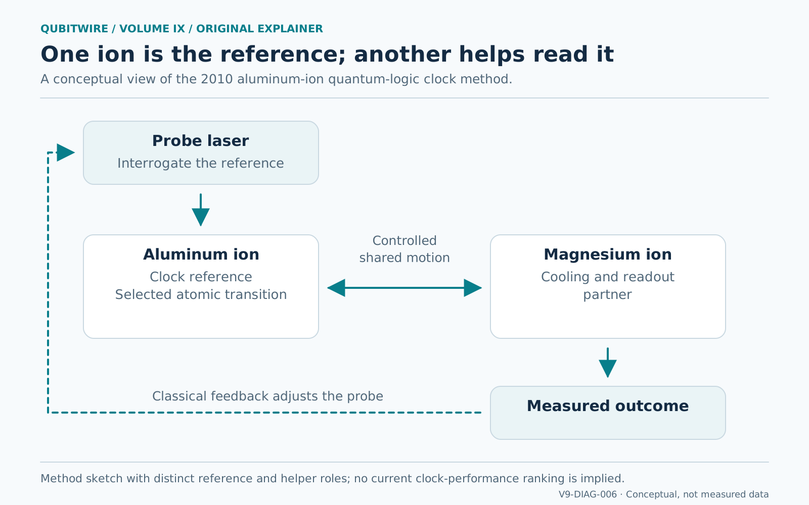
A probing laser interrogates an aluminum-ion clock reference. A magnesium partner supports cooling and readout, linked through controlled shared motion. The measured outcome informs a classical feedback loop that adjusts the probe. The diagram describes the aluminum-clock method and not the separate mercury trap photographed on a penny.
Conceptual explanation; not an apparatus construction drawing or a measured result. Original QubitWire explanatory diagram.
Sources and further reading
- Ion Trap (5881388433) ↗J. Bergquist and D. Wineland / NIST
Mercury-ion optical-clock trap on a penny; original asset credit and public-domain basis.
- NIST’s Second Quantum Logic Clock laboratory photograph ↗J. Burrus / NIST
2010 photograph of James Chin-wen Chou and clock apparatus.
- David Leibrand and Quantum Logic Clock ↗Burrus / NIST
2013 apparatus photograph; the correct scientist surname is Leibrandt despite the file-title spelling.
- NIST’s Second Quantum Logic Clock Based on Aluminum Ion ↗NIST
2010 method: aluminum reference, magnesium partner, cooling/readout and clock comparisons.